Heartwarming Tips About How To Draw Bevel Gears
Bevel Gear: What Are They? How Do They Work? Types And Uses

Solidworks Tutorial | Bevel Gear And Pinion Mechanism In - Youtube

How To Sketch Bevel Gear In Solidworks - Youtube

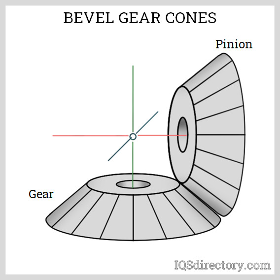
Bevel Gears

Bevel Gear - Wikipedia

Bevel Gears | 3d Cad Model Library Grabcad

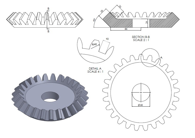
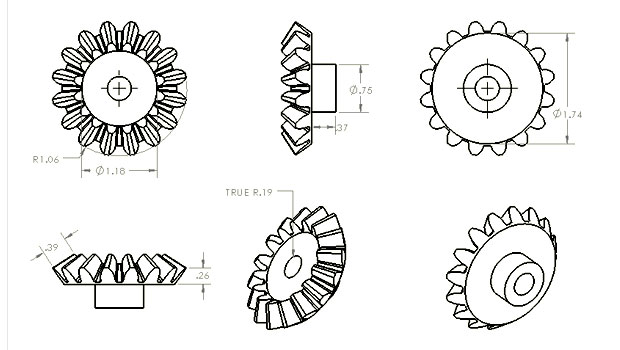
Layout sketch for bevel gear.
How to draw bevel gears. Then provide tooth specs and. If the final product of your project is a technical drawing, you could model the gears with no teeth, using the pitch diameter. Input the following parameters in our free gear dxf generator:
If a gear is mounted on a shaft far from the bearings, the shaft may bend. Design the gear box, shaft. Click new double click part in the new tab to create a new part document.
For the small gear the angle is 360/10 = 36º, giving 18º on either side of the construction line. Design accelerator works at the assembly level so that it can use exisiting geometry to help determine the gear size. We recommend designing bevel gears to be as close to the bearings as possible.
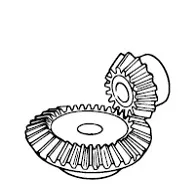
Bevel gearing is used extensively in the automotive industry for the differential gearing connecting the drive shaft to the back axle of motor vehicles. You can support our channel for more tutorials.how to draw bevel gears | solidworks tutorial solidworks mold tools: Draw line from the center of the circle of step 1, to the left with a length of 3492 and an angle of 180 degrees draw a circle on the end point of this new line make an offset of the circle of step.
Then draw the root cone line starting at the root apex point with an angle of 67.88° versus the lower, negative part of the gear axis (root angle, item 4). Cone angle calculated using the gear. Share share this awesome tutorial with your friends.
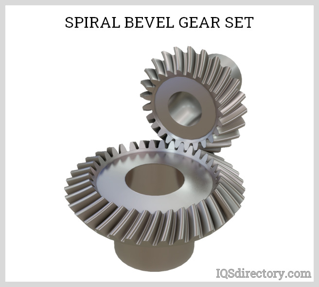
How to use a spur gear generator. In this small video you can see how to make angle grinder spiral bevel gear in solidworks, using flex(twisting) feature.

Straight Bevel Gear - An Overview | Sciencedirect Topics

Creo Tutorial - How To Draw An Involute Bevel Gear Part 1 Youtube
Bevel Gear: What Are They? How Do They Work? Types And Uses
Types Of Gears | Khk Gear Manufacturer
Gear_design.jpg

Help - Bevel Gear Generate ? Autodesk Community Inventor
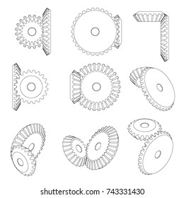
1,233 Bevel Gear Images, Stock Photos & Vectors | Shutterstock


Bevel Gear | Chen Zhonghua Taiji Academy Phone: 780-413-0454
Types Of Gears | Khk Gear Manufacturer

Bevel Gears - An Overview | Sciencedirect Topics
1,233 Bevel Gear Images, Stock Photos & Vectors | Shutterstock
